August 8 th 2022
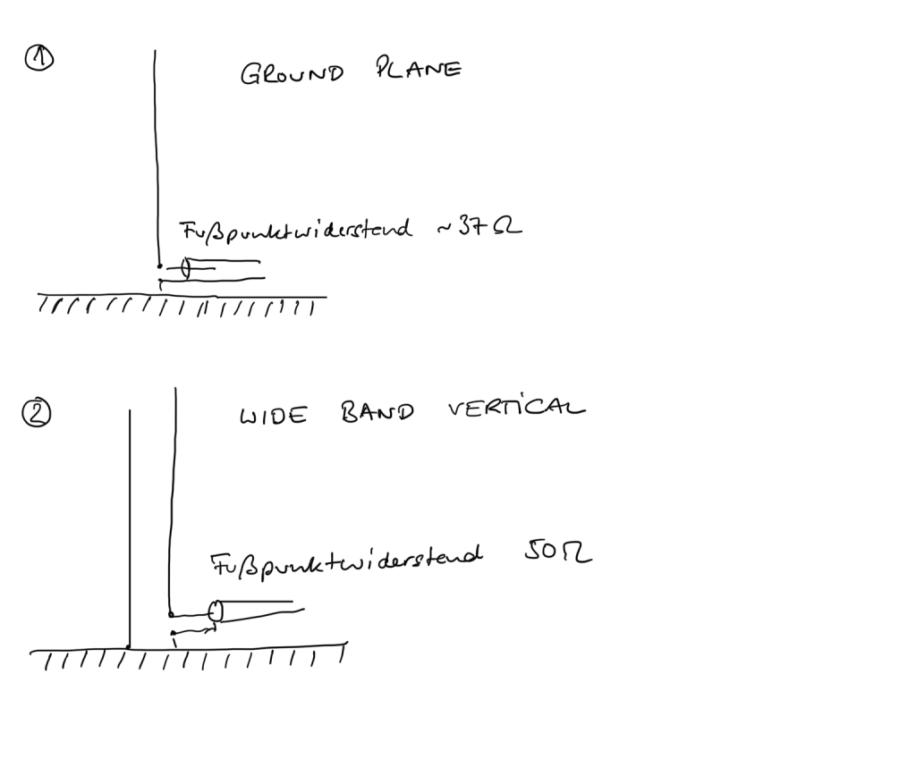
How it started – studies on groundplane antennas
This post is published under a creative commons license CC-BY-SA-NC 2.0. Please check the details here. You may share and use for non commercial purposes but please always cite this website as the genuine source.
The usage of antennas over a wide range of frequencies has always been a design goal both for ham radio antennas and for commercial / military and research purposes as well.
This post introduces a – to my knowledge – all new concept to extend the bandwidth of ground plane antennas.
I started studying the known groundplane antenna and tried to optimze it to cover the entire (Region 1) 80m amateur radio band from 3500 to 3800 kHz. In the end I used two solutions to extend the bandwith of the groundplane aerials compared to quarterwave groundplane made out of wire [fig.1]:
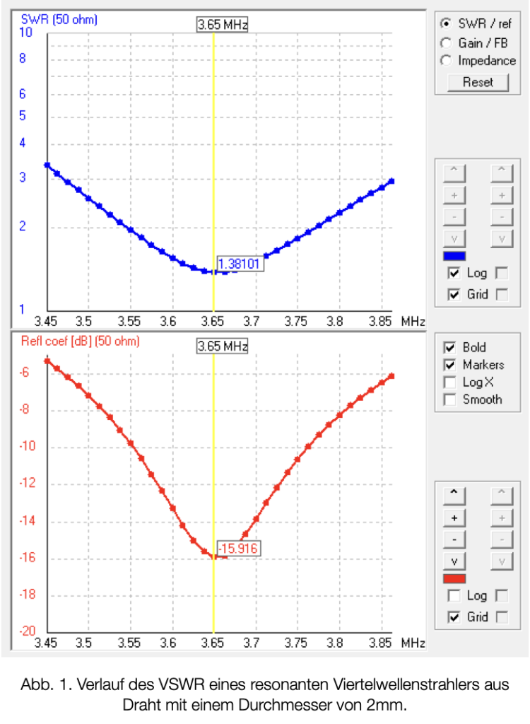
Fig 1: resonant quarterwave groundplane antenna, wire aerial
1. the aerials I use have a electric diameter of about 4 inches / 10 cm. Compared to a wire conductor it is already a „thick“ aerial which already has a wider range auf low return loss ( or VSWR) [Fig 2.].

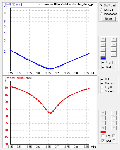
2. Next I extended the electric lenght of the quarter wave ground plane aerial by about 17 %. This shifts the quarter wave resonance well below the ham radio 80m band (resonance frequency is around 3.2 MHz). By feeding this aerial with a series capacitor at the base you can easily tune your antenna to the desired resonance frequency. The current maximum in the aerial moves upwards and you can acheive a real 50 Ohms feedpoint resistance at resonance [Fig 3.]
The groundplane antennas can be used with a better than – 10 dB refl. coeff. over the entire (Region 1) 80m band. The minimum refl. coeff. is about – 27 dB [fig. 3].
For some future extension of a phased array of groundplane antennas I needed / wanted even a even higher bandwidth and I started experimenting again. Actually I started software based simulations using Arie Voors outstanding (and free) 4NEC2 antenna simulation software. Thanks Arie for offering this beautiful tool to the ham community for free! (The simulations are based on a NEC2 extended Kernel with average MiniNec ground)
Of course one never starts from scratch. Gary Breed, K9AY developed the principle of a coupled-resonator dipol. Another approach for dipols and Yagi antennas is known from Jim Breakall, WA3FET who also invented the state of the art Optimized Wideband Antennas (OWA). An older approach for Yagi antennas is known from DL6WU. The idea behind the later two approaches is to use a second, radiation coupled aerial in close proximity of the driven element to higher the feedpoint resitance and extend the bandwith of the (yagi-) antennas.
The WBV concept uses a similar approach with a few crucial modifications.
Wide Band Vertical groundplane antennas (WBV)
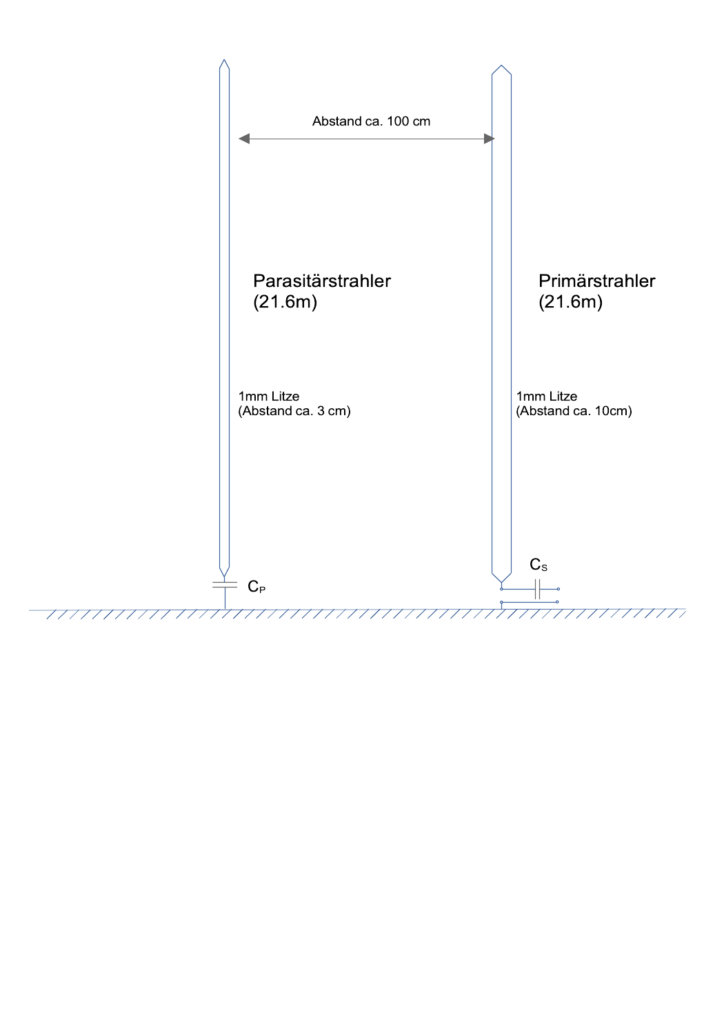
The basic concept of the Wide Band Vertical is a second parasitic element close to the driven aerial. It not driven but just connected to the „ground plane“ that´s why I call it a parasitic element. Fig 2.shows the basic cell.
Compared with the work shown above the WBV approach opens a new dimension of broad band vertrical antennas [Fig. 5]:

The best conventional approach I chose in Fig. 3 has a better than -18 dB return loss of about 130 kHz.
The WBV approach has a better than -18 dB return loss of more than 300 kHz (based on the protoype results, the simulation is even much better)!
There are some crucial aspects, when designing a WB Vertical. Your excited element (fed aerial) becomes longer than the regular quarterwave resonance length of the lowest frequency. The parasitic elements becomes shorter than the quarterwave resonance of the highest frequency.
(On 80m) The parasitic element should have a diameter of about 1 inch or 25 mm. A good starting point for the driven element is a diameter of 3 times the diameter of the parasitic element. Absolut values and the ratio of the diameters are a crucial factor in the WBV design.
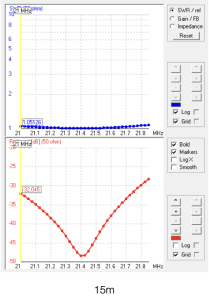
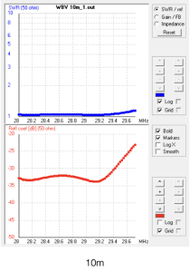
Here a some examples of WBV antennas for the different bands. Alle examples are based on about quarterwave elements. So at least for me the 160m example is more an academic one. Most examples are designed for a flat curve of the refl. coeff.. For the 15m example I tried to optimize the refl. coeff. / VSWR just as an academic excercise.
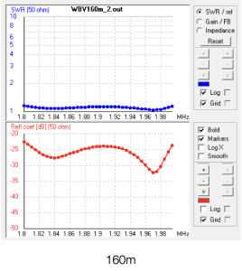
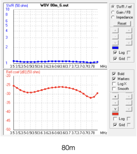
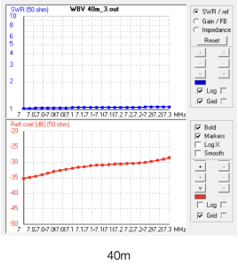
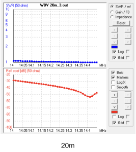
Of course these are simulations! So be cautious!
WBV Prototype measurements
Here is the real world based on measurements at an 80m prototype:
(primary and parasitic aerial of equal length = 21.6m, Serial capacitors of about 2000pF for the primary aerial and around 250 pF for the parasitic aerial, different diameters based on parallel wires connected at the base and the top, ground network of about 15 radial wires on moistured rich ground.). Measurements were made with a DG8SAQ Vector Network Analyzer.
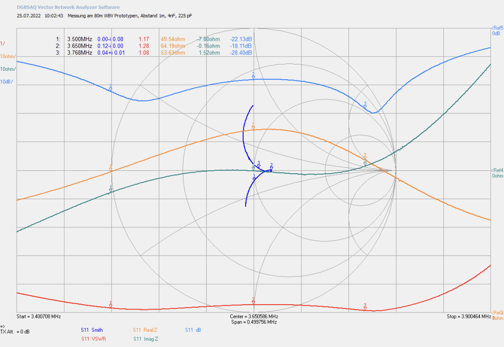
The absolute figures of return loss are not quite as good as the simulation (refl. coeff. of better than -25 dB versus better than -18 dB or an VSWR < 1.28 over the entire band) but the characteristics of return loss, X and R are excactly as simulated). I designed this antenna for 80 m DXing. The DX windows are in the lower CW band segment around 3510 kHz and the SSB DX window from 3775 to 3800 kHz.
Before we discuss the measurment in detail let´s take a look on a regular groundplane antenna and the WBV based on the Smith diagramm based on the simulations:
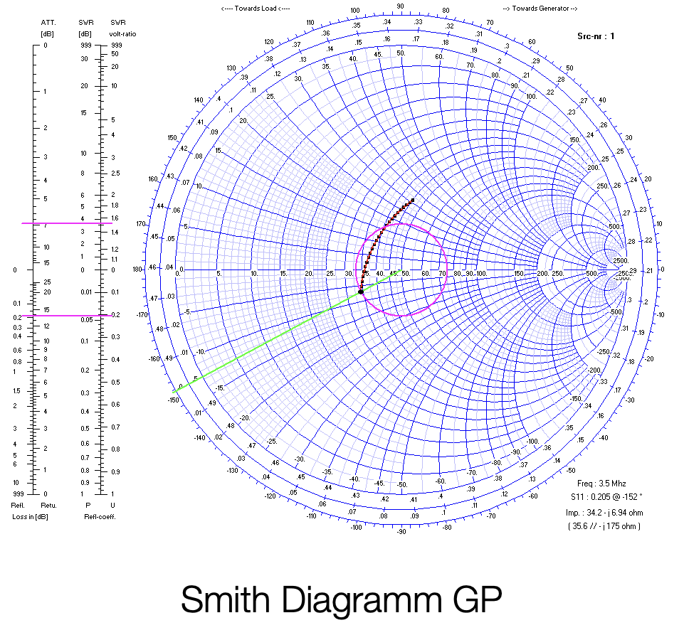
While a regular groundplane antenna (as well as most other antennas) show a curved line from the capacitive lower half of the Smith diagramm to the upper inductive upper half of the Smith diagramm the WBV is a kind of a circle around the (reel) 50 Ohm centerpoint.
The green curve in the measured Smith diagramm above [Fig. 8] shows the variation of the imaginery part of the feedpoint impedance. As you can see – there neither a lot of variation over the entire band nor there is a significant imaginery part. Actually the magnitude of X < +/- i8 Ohms over the entire band.
There is a bit of variation of the real part of Z. Starting and ending at 50 Ohms at the lower and upper end of the band and reaching a maximum of 64 Ohms in the middle of the band resulting in the 1.28 VSWR as there is NO imaginary component involved. A working title for this type of ground plane antennas was „Zero X“ antennas as there´s almost no imaginery component of the feedpoint resitance over the entire bands.
The red curve in Fig. 8 shows the VSWR starting with 1.17 at 3500 kHz and ending at about 1.1 at 3800 kHz. The worst VSWR is in the middle of the band around 3650 kHz at 1.28.
The working principal becomes obvious when doing a deeper analysis of the simulation results:
Starting from the lower frequencies the primary / fed aerial is carrying the antenna current. When moving up in frequency more and more current is coupled in the parasitc aerial. The impact is that the radiation center of the WBV becomes frequency dependend! This offers some interesting chances for usage in phased arrays as the electric distance between the aerials becomes less frequency dependend.
WBV radiation patterns
The WBV concept only affects the frequency dependence of the feedpoint resitance! The horizontal radiation pattern is only slightly distored by the parasitic element which shouldn´t be noticable for a single vertical. The distortion is frequency dependend! For usage in phased array´s it is supposed to compensate in most cases. This is an result as depending on the frequency there´s is either the primary aerial working with a bit of impact by the parasitc aerial or vice versa.
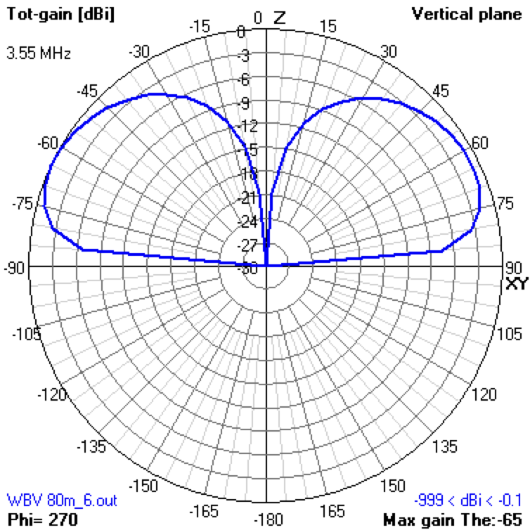
The vertical radiation pattern is basically the same as of a regular quarterwave groundplane antenna. The changed distribution of the antenna currents along the aerial has only little impact on the radiation pattern:

So far I build up prototypes for 80 and 20m as well as for a number of VHF frequencies.
WBV UHF examples
Here is an example of a UHF WBV antenna:

The WBV concept is versatile! It can be used to optimize ground plane antennas for minimum return loss over the entire band [Fig. without further matching elements or for extending the frequency range of a ground plane antenna.

How to design your WBV?
This guideline gives you a good starting point. Each of the parameters can be varied.
Start with the center frequency \( f_{c} \) of the band you want to design your antenna for.
katex
The according wavelength \( \lambda_{c} \): \( \lambda_{c} = c/ l_{f} \)
A good starting point is a lenght \( l_{f} \) of the primary (fed) aerial about 3% longer than a quarter wavelength: \( l_{f} = \lambda_{c}/4*1.029 \)
The length \( l_{p} \) of the parasitic aerial is significantly shorter: \( l_{p} = \lambda_{c}/4*0.887 \)
The distance between the fed aerial and the parasitic aerial \( d \) is: \( d = 0.02*\lambda_{c} \). This is much closer than in the OWA Yagi concept were the distance is around \( 0.05*\lambda_{c} \)
The concept is needs different radius the fed and the parasitic aerial for best performance: \( r_{f} = 10^{-3}*\lambda_{c} \)
The radius of the parasitic aerial is: \( r_{p} = 1/3*r_{f} \)
This instructions workes well for a simulation approach.
In practice I use equal length \( l_{f} \) and \( l_{p} \) about 10 to 15% longer than the quarterwave resonance length and tune both aerials with serial capacitors until I get the desired performance across the band.
Outlook
The WBV concept has interesting applications in multiband vertrical antennas and phased arrays. There´s more to come…
Summary
By introducing the Wide Band Vertical antenna concept:
- adding a parasitic element /aerial close to the fed groundplane aerial in a certain way as described above
it is possible to design groundplane quarterwave vertical antennas with unique features:
- feedpoint resistance \( Z=R+iX \) around \( R= 50 \text { Ohms} \) almost purely real
- very little variation of the imaginery component of the feedpoint resistance \( |X| < 8 \text{ Ohms} \) for a 80m WBV
- very low reflection coefficient / VSWR over the entire ham radio bands
- very low reflection coefficient for commercial broad band applications (hf, vhf, uhf …)
- no significant changes of both the vertrical and horizontal radiation patterns compared to regular groundplane antennas
- no lossless components
- no matching networks
Good luck with your experiments!
Joerg Suessenbach (PhD), DF9LJ
Copyright CC-BY-SA-NC 2.0
/katex
References:
about DL6WU Yagi antennas: R.B. Cebik, W4RNL: http://on5au.be/content/a10/vhf/wu.html
Nathan Miller, NW3Z, Jim Breakall WA3FET: https://naic.edu/~angel/kp4ao/ham/owa.html
Schreibe einen Kommentar